How to Solder a Through-Hole Component, Step by Step
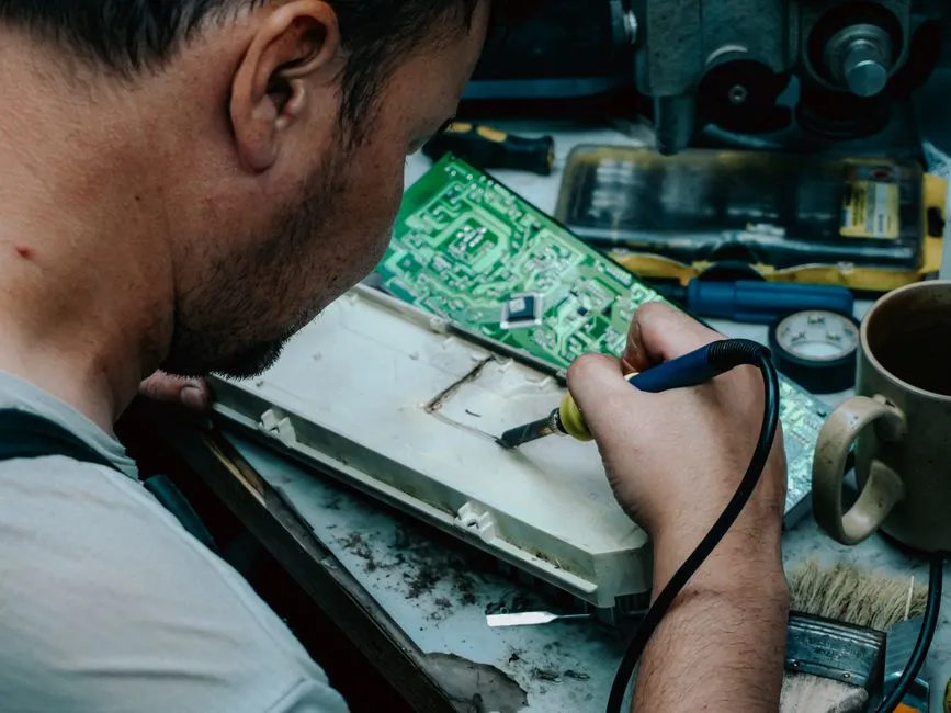
- How do you solder a through-hole component?
- What must be ready before the iron is switched on?
- How should the hot-work area be arranged?
- Step 1: Can you identify and secure the part without heat?
- Step 2: Is the approved tip ready?
- Step 3: Heat the pad and lead together
- Step 4: Withdraw, cool and trim as directed
- What should you inspect before attempting another joint?
- How can you record a useful first attempt?
- How do you finish the session?
- Sources
How do you solder a through-hole component?
To solder a through-hole component, secure it in a new, never-powered practice board, heat the pad and lead together, feed the specified solder into their junction, then withdraw the solder before the iron and let the joint cool undisturbed. Follow the kit and tool instructions with a qualified instructor, eye protection and suitable fume extraction. Stop for poor wetting or damage; do not improvise rework.
This is a manual-led learning sequence for a documented educational practice board, not a repair procedure or a substitute for supervised training. We have not tested a particular kit. The board stays disconnected from batteries, USB and every other power source throughout. Do not use salvaged electronics, mains circuits, charged equipment or damaged battery assemblies for this exercise.
A through-hole component has leads that pass through holes in the printed circuit board, or PCB. The pad is the conductive landing around a hole. On a plated through-hole board, the hole also has a conductive lining. Identify those features on the kit's assembly drawing before selecting a joint. Related component terminology belongs in our project fundamentals collection.
What must be ready before the iron is switched on?
Select the actual kit, solder, flux and iron together with an instructor competent in electronics soldering and the equipment being used. Read their instructions and safety data sheets. The University of Illinois soldering safety guidance calls for training, manufacturer instructions, hazard assessment and protective equipment. A beginner's first attempt should not depend on identifying an unfamiliar material from appearance.
Write a short setup record:
- Kit name, board revision and the assembly-instruction page.
- Component designation and supplied part identification.
- Specified solder alloy, flux system and wire size.
- Approved iron tip, temperature setting and heating-time limit.
- Cooling, lead-trimming and residue-cleaning requirements.
These are fields to resolve, not values to guess. If the documentation does not settle the heating process, ask the kit manufacturer and instructor before heating anything. A generic tutorial's setting is not a replacement for the instructions for the actual combination of board, component and consumable.
Keep the practice board separate from all power leads. UC Merced's soldering training explicitly prohibits soldering a powered PCB. “Never powered” is the tighter boundary chosen for this exercise: there is no troubleshooting, capacitor discharge or energizing step.
How should the hot-work area be arranged?
Wear safety glasses appropriate to the task, including during wire cutting. Keep the iron in its manufacturer's stable stand whenever it is not being used. Keep hot metal and the tip away from skin, cords and flammable materials; never hold a heated component with bare fingers. Inspect the tool and cord before use and stop if damaged. Illinois identifies burns, electrical faults, chemical exposure and flying fragments as distinct hazards.
Provide clear lighting so the pad and adjacent conductors are visible. Harvard's soldering procedure specifies a stable heat-resistant setup, eye protection, fume extraction and suitable lighting. Have the instructor confirm any additional protective equipment for the materials and process. Do not open or modify the iron or its power equipment.
Fume control is separate from eye and burn protection. Rosin-based flux fume can cause occupational asthma. The Health and Safety Executive's soldering guidance calls for extraction, keeping the head out of the plume and avoiding overheating. Have a competent person confirm suitable, maintained local extraction for the actual solder and flux; do not assume an open window or an ordinary desk fan establishes adequate control. An extractor must be positioned and maintained according to its instructions. Lead-free labeling does not remove the need to assess flux fumes.
Step 1: Can you identify and secure the part without heat?
Use the kit's drawing to find the component position and specified orientation. For a practice resistor, match its designation and value to the parts list; this article does not prescribe a substitute resistance. With the iron still off and cool, insert the supplied leads as directed. Do not force a component into mismatched holes.
Secure the board in an appropriate holder and retain the component using the kit's method. Verify that both pad and lead remain accessible and that the holder does not obstruct the working area. Adafruit's preparation guide emphasizes clean surfaces and preventing component movement. Contamination or unstable positioning needs attention before soldering.
Rehearse without touching the board with a hot tool: point to the intended tip contact, solder-feed location and return path to the stand. Ask the instructor to confirm the sequence. This cold rehearsal is our editorial learning aid, not a claim that rehearsing alone establishes competence.
Step 2: Is the approved tip ready?
Under supervision, prepare the iron using its manufacturer's cleaning and tinning method. Tinning means leaving the specified thin solder coating on the working surface; use the prescribed cleaning accessory, not a file or an improvised abrasive. Adafruit's preparation guidance describes cleaning and tinning before a joint is made.
Confirm the recorded temperature and process limit before approaching the board. Do not increase the setting merely because a previous attempt did not work. For this first exercise, missing instructions or uncertainty about the tip's condition are reasons to stop and ask the instructor.
Step 3: Heat the pad and lead together
Place the prepared tip so it contacts both the pad and the component lead. Feed the specified solder wire to their heated junction, touching the pad and lead rather than depositing a melted blob from the iron. Watch whether it wets both surfaces: wetting means the molten solder spreads onto them rather than remaining an isolated bead.
Adafruit's joint-making sequence illustrates heating both surfaces and feeding at the junction. The objective is the specified joint, not a large accumulation of solder.
Keep within the approved heating-time limit. If solder does not flow as expected, withdraw the tools, return the iron to its stand and let the assembly cool for instructor review. Do not press harder, extend heating indefinitely or repeatedly attempt the same pad. This guide supplies no universal number of seconds because no specific kit, tip, alloy or component has been selected.
Step 4: Withdraw, cool and trim as directed
When the required solder has flowed, remove the solder wire first, then withdraw the iron and return it to the stand. Keep the board and component still while the joint solidifies. UC Merced's training uses this withdrawal order. Do not touch the joint to check its temperature.
After cooling as the kit requires, trim only the excess component wire leads identified for trimming in its instructions. Adafruit distinguishes these from connector or socket pins, which should not be treated as disposable excess wire. Use suitable cutters and the instructor-demonstrated fragment-control method; keep eye protection on. If the intended cut position or tool suitability is unclear, leave the lead uncut for review.
What should you inspect before attempting another joint?
Use the kit's acceptance illustration and instructor review. Do not apply a universal “shiny equals good” rule: Kester's hand-soldering FAQ explains that common lead-free solders can have a duller finish.
Look separately at these observations:
- Solder has wetted both the pad and lead, not just one.
- No unintended solder bridge joins neighboring conductors.
- No movement was observed while the joint solidified.
- The pad remains attached, without visible lifting or other damage.
Adafruit's problem guide distinguishes disturbed joints, insufficient wetting, bridges and lifted pads. A cold joint involves solder that did not melt fully; a disturbed joint involves movement during solidification. A beginner should record what was observed rather than diagnose either from shine alone.
Any suspected defect means stop, cool and ask the instructor. Do not scrape a bridge with a blade, pull a component out, add more solder repeatedly or attempt pad repair. Visual inspection also does not authorize powering the board. Testing and commissioning are outside this exercise.
How can you record a useful first attempt?
Use this original observation sheet with the instructor. The example assumes a practice resistor with two wire leads, so there are two intended joints. It is not a report from a tested kit.
| Observation | First lead | Second lead |
|---|---|---|
| Component remained secured | Record what happened | Record what happened |
| Pad wetting visible | Record or mark uncertain | Record or mark uncertain |
| Lead wetting visible | Record or mark uncertain | Record or mark uncertain |
| Adjacent conductors free of unintended bridge | Record or mark uncertain | Record or mark uncertain |
Two joints multiplied by four observations gives eight recording fields. That count is not eight safety tests or a quality certification. Add a separate note for visible damage, questions and the instructor's next action.
For example, a hypothetical record might say: “First lead: solder visible on lead, pad wetting uncertain; stopped. Second lead: not attempted.” That is more informative than “bad joint.” It identifies the unresolved observation without inventing a cause or implying that another heating cycle is appropriate.
How do you finish the session?
Switch off and unplug the iron according to its instructions and let it cool in the stand before storage. Keep food and drink away from the work area, collect clipped leads and solder debris using the prescribed cleanup method, and wash hands after handling the materials. Follow the safety data sheets and local disposal requirements. Illinois covers these hygiene and waste controls.
Use only the kit and flux manufacturer's specified residue-cleaning process. Do not introduce an improvised solvent or clean a hot assembly. Leave unresolved contamination for the instructor rather than choosing a cleaner by availability.
Label the board with its review status and keep it unpowered. File the setup record with the observations, including any instruction that still needs clarification. Further topics are grouped in soldering and repair; they do not extend this exercise into unfamiliar equipment or authorize unsupervised rework.