How to Continuity-Test a Circuit Safely
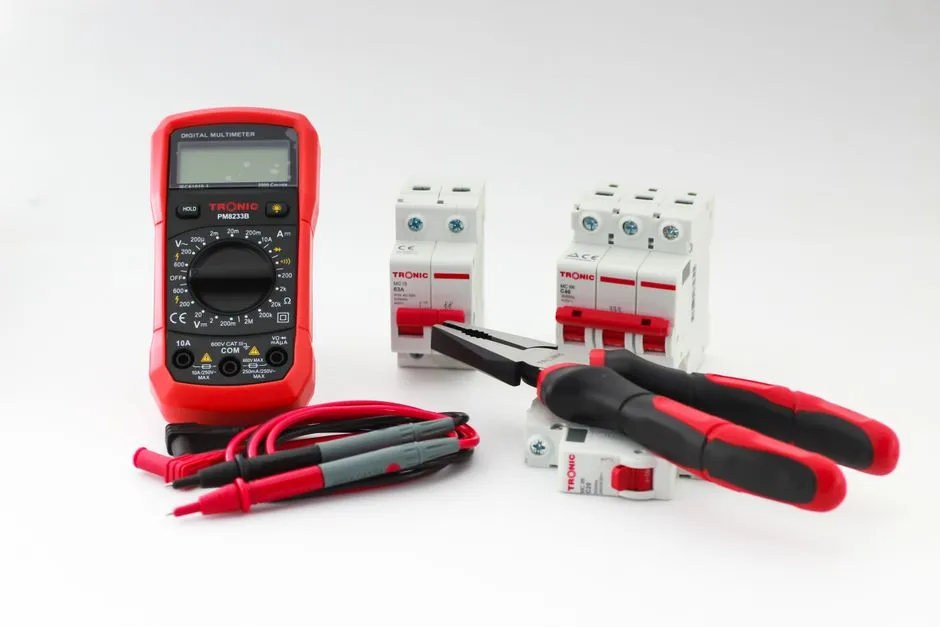
Continuity mode asks whether resistance is below a threshold
The meter applies a small test signal and beeps when the measured path meets its instrument-specific threshold. A beep does not mean perfect zero resistance, high-current capability, correct wiring, or safety. Read the meter manual for threshold, response, and test voltage.
Use this method only on known low-voltage electronics with every external source disconnected.
Deenergize and handle stored energy
Unplug the supply, disconnect batteries, and follow the circuit's documented discharge method. Verify the meter is in the correct jacks and a voltage mode check shows no unexpected energy where the test will occur. Capacitors can recharge through dielectric effects or another connected source, so reassess before touching.
Do not short capacitors with tools. If voltage, energy, or isolation is unknown, stop and use qualified service.
Prove the meter setup
Inspect the meter and leads, select continuity, and touch the probes together to learn the response. Separate them to confirm the indication changes. This checks the immediate test path, not the meter's suitability for hazardous circuits.
Keep fingers behind probe guards and use clips where they prevent slips.
Predict the expected path from the schematic
Identify the exact two nodes and everything between them. Switches, fuses, coils, traces, connectors, resistors, semiconductors, and parallel branches can all affect the reading. Record whether you expect an open, low resistance, changing capacitor charge, or a semiconductor-dependent result.
Use schematic node reading instead of beeping randomly around a board until optimism develops.
Test wires and traces in sections
For a wire, probe the conductor at both documented ends without damaging insulation or spreading terminals. Flex only as the manufacturer permits while watching for intermittency. For a PCB trace, test between accessible pads, then narrow the section around vias, connectors, or suspected damage.
Never force a probe into a connector. Use suitable breakout or back-probe accessories.
Interpret a beep in context
A protection diode, transformer winding, relay coil, low-value resistor, or another parallel circuit may create continuity that is normal. A corroded connection can beep under tiny test current yet fail under operating load. A fuse may show continuity but still have poor holder contact.
Switch to resistance mode where useful and compare with specifications. For operational resistance faults, voltage-drop measurement under controlled power may be required by the service procedure.
Check for shorts before power
Measure between each supply rail and return, then compare with the design. Low resistance can be normal for heaters, motors, large input capacitors during charge, or dense electronics. Reverse probe direction where semiconductors affect the result and wait for stable behavior.
Do not declare a short from one beep. Inspect the PCB for damage and isolate sections logically.
Verify after repair
After correcting a trace, wire, connector, or solder joint, retest the intended path and adjacent nets for accidental bridges. Inspect mechanically, restore covers and strain relief, then power the isolated low-voltage circuit through an appropriate current limit.
Continuity is excellent at answering a narrow question. Ask it “Is the whole device good?” and it will beep with the confidence of someone who did not hear the question.