How to Inspect a PCB for Damage
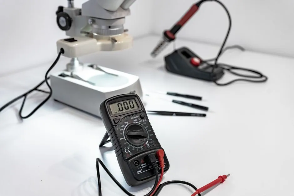
Establish safety and board identity
Identify the equipment, board revision, supply, batteries, and possible stored energy before opening anything. Work only on known isolated low-voltage assemblies within your training. Mains, high-voltage, microwave, CRT, medical, safety, pyrotechnic, grid-connected, and damaged battery products remain closed for qualified handling.
Disconnect sources and follow the documented discharge and ESD procedure.
Document before cleaning
Photograph the board straight on and at angles, both sides where accessible, before moving wires or removing residue. Record connector positions, polarity, fasteners, shields, thermal pads, insulation, and cable routing. Mark the exact symptom and recent repair area.
Cleaning first can erase the direction of a leak, arc track, impact, or overheated component.
Scan for heat and electrical stress
Under bright angled light and magnification, look for discoloration, char, cracked packages, vented capacitors, melted insulation, darkened solder, lifted mask, delaminated laminate, blown fuses, solder splash, and metal debris. Compare repeated channels and nearby components.
Charred board material may become conductive and can compromise clearance. Do not simply bridge across it and power up.
Inspect mechanical damage
Check mounting holes, board edges, heavy components, transformers, connectors, switches, jacks, relays, heat sinks, and tall capacitors for cracked joints, torn pads, bent pins, missing fasteners, or stress. Look for board flex marks and traces broken near screw points.
Strain-relief failure can make a perfect solder joint carry cable force until it stops being perfect.
Look for liquid and corrosion paths
Identify residue, green or white corrosion, mineral deposits, sticky contamination, rust, mold, and tide lines. Wear appropriate protection and do not handle unknown or battery leakage. Liquid can travel under packages, shields, connectors, and vias beyond the visible stain.
Use a flux- and material-compatible cleanup process only after documenting the evidence.
Inspect prior rework
Look for mismatched alloy, excess flux, bridges, scorched mask, scraped traces, jumper wires, lifted pads, replaced components, missing parts, and incorrect polarity. Verify modifications against the schematic rather than assuming every bodge wire is either brilliant or criminal.
Use continuity testing on defined deenergized paths and compare with expected parallel circuits.
Check solder joints systematically
Inspect power and ground connectors first, then heavy or hot parts, repeated flex points, fine-pitch pins, and the symptom's functional block. Good-joint criteria include wetting, solder volume, alignment, intact pads, and absence of bridges—not shine alone.
Do not diagnose only by sight
A cracked multilayer via, semiconductor fault, contaminated high-impedance node, or capacitor with degraded electrical properties may look normal. Conversely, a dark adhesive or manufacturing residue may be harmless. Connect each clue to measurements, schematics, and known-good behavior.
Decide whether the board is repairable
Stop for carbonized laminate, internal-layer damage, widespread corrosion, safety-isolation damage, inaccessible liquid, burned high-energy sections, battery leakage, counterfeit or missing documentation, or a repair that cannot restore mechanical support and clearance. Replacement or professional rework may be safer and more economical.
After any low-voltage repair, inspect again, check adjacent shorts, restore insulation and strain relief, then power through an appropriate current limit. The microscope is a witness, not a judge; it sees everything and understands none of it without the circuit.