Multimeter Modes and Lead Jacks Explained
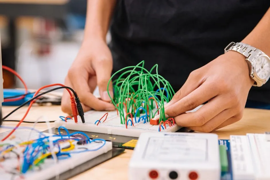
The meter setup is part of the circuit
A digital multimeter can measure voltage, resistance, continuity, diode behavior, and current, but each mode changes how the instrument connects internally. The lead jacks, selector, category rating, fuses, maximum input, and test environment all matter.
Read the exact meter manual. This guide stays with isolated low-voltage hobby circuits; it does not authorize mains or high-energy measurement.
Inspect before every use
Check case, display, battery indication, selector, lead insulation, finger guards, probe tips, connectors, jacks, and current-input fuses through the manual procedure. Do not use cracked, contaminated, modified, or uncertified equipment.
A meter rating is not transferable to damaged leads, improvised adapters, or a user working beyond training.
Voltage mode connects in parallel
Place the black lead in common and the red lead in the voltage/resistance jack, select the correct AC or DC function and range, then connect across two circuit points. Confirm expected magnitude and polarity first.
Use clips with power off when possible, then energize without hands near exposed conductors. Keep probe tips from bridging adjacent pins.
Resistance and continuity require no external power
The meter supplies its own test signal in resistance, continuity, and diode modes. Disconnect every power source and battery, handle stored energy through the documented method, and verify deenergization before connecting. External voltage can damage the meter or create misleading readings.
Read continuity-test safety because a beep indicates a threshold, not automatically a perfect zero-ohm path.
Current mode goes in series
To measure current, the circuit must be opened and the meter inserted into the intended path using the correct current jack, mode, range, fuse, and polarity. Placing a meter configured for current directly across a supply can create a near short, blow the meter fuse, damage the circuit, or cause an arc.
Start with a suitable higher range when the expected current is uncertain but remains within the meter and circuit instructions. Never move the selector or lead between jacks while connected unless the manual explicitly permits it.
Return the lead immediately
After any current measurement, deenergize, remove the meter, restore the circuit, and return the red lead to the voltage/resistance jack. This habit prevents the classic next-day mistake of attempting a voltage measurement with the meter still dressed as a wire.
Know what the meter cannot prove
An open-circuit voltage can look correct while a source collapses under load. Continuity can pass through an unintended parallel path. Resistance in circuit can be lower than the component value. Diode mode depends on test voltage and current. Compare readings with the schematic, datasheets, and test conditions.
Bench-supply current limiting protects a project differently from inserting a meter in current mode.
Stop at hazardous energy
Unknown equipment, mains, inverters, large capacitors, microwave, CRT, motor drives, solar strings, electric vehicles, medical devices, and damaged batteries require task-specific ratings, PPE, isolation, and qualified procedures. OSHA workplace guidance emphasizes deenergizing exposed parts and verifying with suitable inspected test equipment by qualified people.
Use the repair stop conditions before removing a cover. The meter is not a magic wand; held in the wrong configuration, it is simply a very expensive jumper wire.